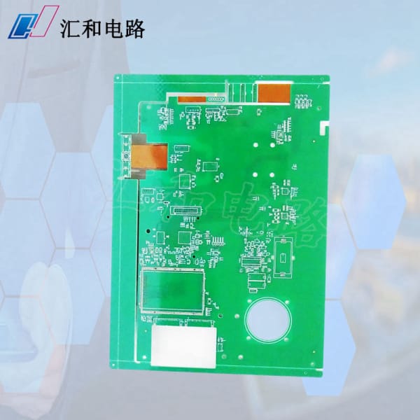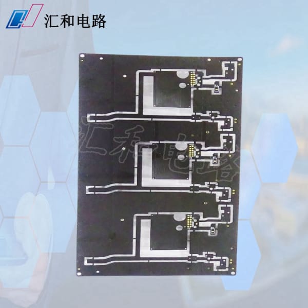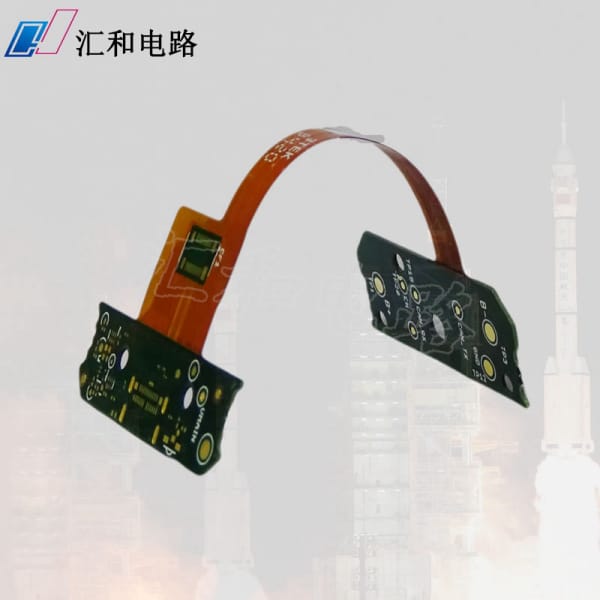
PCB (Printed Circuit Board) board, also known as printed wiring board, is an essential component in modern electronic devices. It plays a vital role in connecting and controlling the various components of electronic devices. The following article outlines the PCB board manufacturing process flow, including design, fabrication, and assembly.
1. Design
The first step in the PCB board manufacturing process is PCB design. Engineers use electronic design automation (EDA) software to create the PCB layout, including the placement of components, trace routing, and via placement. After completing the design, the file is converted into Gerber files to be used during the fabrication process.

2. Fabrication
The fabrication process begins with the fabrication of the board base material. PCB boards are typically made of a fiberglass reinforced epoxy resin. The base material is cut into the required size and shape according to the layout design.
The fiberglass base material is then coated with a thin layer of copper, which acts as a conductor. This copper layer is typically around 1 ounce per square foot, but it can be varied as per requirements.

Next, a layer of photoresist material is applied to the copper layer. The photoresist material protects the copper layer from acid solution during the etching process. The Gerber files are used to create a film, which is then used to create a photographic negative.
The photographic negative is placed on the copper-coated board, and it is then exposed to ultraviolet light. The light hardens the photoresist material in the areas not covered by the negative.
After development, areas of the copper layer that are not covered by photoresist material are etched away using an acid solution. The photoresist material is then removed, leaving behind the required copper traces and pads.
3. Assembly
After the fabrication, components are assembled onto the PCB board. This process involves the placement of electronic components onto the board and soldering them to the copper traces and pads.
Surface Mount Technology (SMT) and Through-Hole Technology (THT) are the two major assembly technologies. SMT is the preferred method as it is faster and more efficient. The components are placed onto the PCB board using automated pick-and-placement machines.
The placement of THT components is carried out manually. The components are inserted through holes drilled in the board and soldered in place using a wave soldering machine. THT is typically used for large components such as connectors, diodes, and relays.
4. Testing
The final step in the PCB board manufacturing process is testing. After assembly, the board is tested for electrical connectivity, functionality, and reliability. Automated testing machines are used to test the PCB boards. These machines can detect and report any defects in the board.
Summary
The PCB board manufacturing process involves several steps, including PCB design, fabrication, assembly, and testing. Each step is crucial to ensure that the PCB board functions correctly. The process is highly automated, and manufacturers use advanced equipment to ensure that the boards are manufactured to high levels of accuracy and precision.
In conclusion, the PCB board manufacturing process is an essential part of modern electronics. The process involves several steps that are crucial to ensuring that the PCB board functions correctly. By utilizing cutting-edge technology, manufacturers can produce PCB boards that are highly reliable and robust.
]]>